

My Workbench
By Bob Hamilton
The time had finally come when the frustration of chasing my Workmate around the shop while trying to hand plane a board had built up to the point that I was ready to put all other projects on hold until I finally had myself a decent workbench. I had been intending to build myself a workbench all along, but never seemed to find the time before. Now I had determined to MAKE the time.
I had a picture inside my head of what my bench would look like, sort of a distillation of ideas I had seen in magazines, catalogs, and books. I knew I wanted a very solid, well supported laminated top with bench dog holes for use in conjunction with the front and end vise. My material of choice for the bench top was either hard maple or beech. I already had a front vise that I had picked up at a woodworking show several years back but had never installed anywhere because I didn't have a bench to install it on. I had also decided to go with the Veritas twin-screw vise as my end vise. Due to the small size of my workshop, I felt that the largest I would be able to go was about five and a half feet in length and 2 and a half feet in depth.
 My
available tools were also a factor in my final design. I have
a Delta 12" thickness planer, so I decided to make the slabs
for the benchtop 12" wide with a 4" tool trough between
them. This way, I would be able to do the initial surfacing of
the slabs after glue-up by running them through the planer. I
do not have any power tools that would allow me to make large
section mortises in heavy timbers accurately, so I decided to
simplify things by laminating the material for the supporting
structure of the bench from three layers, leaving gaps in the
middle layer of the lamination wherever I needed a mortise.
My
available tools were also a factor in my final design. I have
a Delta 12" thickness planer, so I decided to make the slabs
for the benchtop 12" wide with a 4" tool trough between
them. This way, I would be able to do the initial surfacing of
the slabs after glue-up by running them through the planer. I
do not have any power tools that would allow me to make large
section mortises in heavy timbers accurately, so I decided to
simplify things by laminating the material for the supporting
structure of the bench from three layers, leaving gaps in the
middle layer of the lamination wherever I needed a mortise.
With all this in mind, I drew a rough sketch and penciled in enough dimensions to allow me to roughly calculate how much material I would need, with a generous allowance for error and waste. I decided to get between 50 and 60 board feet of material for the top slabs, and about 50 board feet for the supporting structure. Off I went to the local sawmill, fully intending to buy 8/4 hard maple or beech for the top, and whatever was available for the understructure.
My luck was running true to form, however, and I arrived at the mill the day after they had shipped almost all the dry wood that they had. They had absolutely nothing suitable for a bench top in 8/4 thickness, so I wound up scratching through a very short stack of already picked over birch in 4/4 thickness to find enough for my top. I was able to get some very nice soft maple in 5/4 thickness for the understructure. I picked out the boards I wanted from the two piles and stood them up against one wall to be measured. When they had been measured, I loaded them in my truck while the manager was making up my bill. I had 64 board feet of birch and 50 board feet of soft maple, for which, due to the slim pickings I presume, I was charged just $1.00 per board foot. (That's $1.00 Canadian, about $ .72 U.S.) The total bill including taxes was $131.10.
My original plan had been to plane the 8/4 wood to 1 3/4" thickness, rip it to 2 1/4", and rotate each piece 90 degrees before gluing up. I figured this would give me two slabs 2 1/4" thick each made up of 7 pieces laminated together. The only thing that my inability to obtain 8/4 material changed was the number of pieces in each lamination. Once I had surfaced the 4/4 birch I found that I needed 15 pieces for each slab. This is a major glue up! I used biscuits to help keep the pieces aligned while the clamps were applied. Let's see, now, that's 8 biscuits per joint, with 14 joints means 112 biscuits or 224 biscuit slots per slab, or 448 slots all together. I hadn't realized before just how heavy that DeWalt plate joiner is!
I had laid out the pieces for each slab and arranged them as much as possible so that the best edge was up, any crown alternated, the grain was arranged to minimize chip out when planing, and the outer pieces were the best ones of the lot. Then I drew triangles across the upper edges to maintain the order. While I still had them together, I laid out for the biscuit slots, staggered so that no two slots were back to back in the same piece of wood. I then cut the slots. Did I mention how heavy my plate joiner is?
I was now ready to glue up the slabs. I stood two straight pieces of 2x4 on edge on top of my table saw to serve as a gluing bench. It did not take long after I started spreading glue before I realized that there was no way I was going to be able to glue all 15 pieces together in one go, given the 20 minute open assembly time of the PVA glue I was using. I managed 7 pieces the first time, and was probably pushing my luck. I used the outside piece from the far edge to protect the gluing face of the 7th piece and applied almost every clamp I own to the assembly. I then left it to cure for about 4 hours, came back, removed the clamps and scraped off the squeeze out. I glued up the other 8 pieces to this assembly and again applied clamps and left it overnight.
The next day, I repeated the process for the second slab. This left me with two slabs about 12 1/2" wide, 2 1/4" thick, and a little over 6 feet long. I tacknailed a straight rip from a piece of plywood to the top overhanging one edge to give me a straight reference to run along the table saw fence and ripped the opposite edge straight. I could then run this newly straightened edge along the fence to straighten the remaining edge. I removed the saw marks with my Makita 3 1/4" power hand planer with the bevel fence set to 90 degrees.
This left the slabs narrow enough to fit through my 12" thickness planer. I planed each face of both slabs just enough to level all the joints and have both slabs equal. I was pleased to find that the slabs were still a full 2 1/8" thick after this operation. I first squared the ends using a portable circular saw, but was not pleased with the finish of the cut surface. I went out and bought a 3/4" flush trimming bit with 1/2" shank for my router, but it only had 2" of cutting edge. I used a 1/2" straight cutting bit in the router to make a trimming cut 1/4" deep across the bottom edge of both ends of the slabs, then used this flat surface to run the bearing guide of the flush trimming bit against as I cut from the top of the slabs. This left a much better finished surface.
With the slabs complete, I turned my attention to the supporting trestles. I planed the soft maple to 1 1/8" thickness and ripped it 3" wide. I then carefully measured and cut the individual pieces for the laminations. Each trestle consists of two horizontal members at the extreme top and bottom, and two vertical members spaced in from the ends of the horizontal members about 6". The vertical members were easy, since each one consisted of only one long piece with a shorter piece on each side. The short pieces form the shoulders of the tenons, and the overhanging ends of the middle long piece become the tenons.
The horizontal members are a little trickier, since spaces must be left in the middle layer of the lamination to form the mortises for the tenons. I initially glued up the outer full length pieces with one short length between them centered on the length. This established the inner end of the mortises. (I used glue and counterbored screws for all of these laminations to avoid problems with parts sliding as the clamps were tightened. I later plugged all the screw holes.) Once the glue was dry and all squeezeout removed, I inserted the tenons of the vertical members in these open ended mortises and used them to index the short piece that forms the outer end of the mortise. I bored pilot holes and screwed these into place without glue. Then I removed the tenons from the mortises, backed the screws out and applied glue to the end pieces. I put them back in position and re-drove the screws.
Once the glue was dry and the squeezeout removed, I marked out for a relief cut in the bottom horizontal pieces so that only the end 6" would be touching the floor. This was not really necessary, since I was planning on installing levelers in them anyway, but I felt they didn't look right without it. I cut this on the band saw, and also made a 45 degree cut from about half way up the ends of each piece to take off the top corner and give them more of a finished look.
Assembling the trestles was more difficult than I had anticipated. The mortises were a very snug fit during the dry run, and with the addition of glue it required a lot of effort, clamps and swearing to get them to draw home. I did succeed eventually, and used a bar gauge to ensure the diagonals were equal before I set them aside to dry. When they were dry I cut the tenons off flush and hand planed the top and bottom surfaces straight and true.
I wanted to use a sliding dovetail joint to attach the slabs to the trestles so that I could use a single lag screw up through the end of the top horizontal member to attach the slabs. This way they would be free to move towards the middle of the bench with the changing seasons. I clamped the two trestles together with the tops flush to give me a broad surface to support the router. I used an edge guide and many passes to machine a dovetail tongue about 1" wide the length of each top member, centered on its width.
Now I had to make the final decisions about dog hole spacing so that I would not wind up with a trestle right under a row of dog holes. I wanted the trestles to be spaced as far apart as possible to provide as much room between them for a storage cabinet as I could. Using trial and error I determined that a spacing of 7" between dog holes gave the best compromise. (More on this later) Laying out the dog hole locations allowed me to determine the best positions for the trestles and lay out the dovetail dado.
At this point I made a serious error in judgment that should have cost me dearly. That it did not was pure, blind luck. The PROPER technique for cutting these dovetail dados would have been to clamp the slabs together side by side and machine the slots in one continuous pass across both slabs to ensure proper alignment. This, of course, never even occurred to me until after I had measured and machined each slot individually, despite the fact that I have used this technique in the past with good results. In this one specific case, however, my mistake actually turned out better than the proper method would have.
I was using a jig I built from one of Patrick Spielman's router books that allows cutting dados with the router and is micro-adjustable for dado width. It took me three tries before I finally got it set to cut the perfect width of dovetail dado, by which I mean that the fourth and final dado cut into the bottom of the second slab was the only one that was exactly right. The first three were close, but still allowed the trestle to rock slightly from side to side when it was inserted into the dado. I resigned myself to having to use two lags into each slab to attach the trestle, and decided to try a full assembly. As it turned out, the slight measuring errors made while locating the dados and cutting them individually actually canceled out the slop from cutting the dados a hair too wide! With the slabs assembled to the trestles, the bench was quite solid even without stretchers between the trestles.
While I had the bench assembled, I measured for the stretchers. Then I took the bench apart and made the stretchers 1" longer than the measurement between the trestles. I chopped out mortises 1/2" deep on the inside face of the trestles, and machined tenons on the end of the stretchers to fit. The stretchers are 6" wide and 1 1/8" thick soft maple. The hardware I wanted to use to attach the stretchers is something that I know by the name of cross dowel nuts, but I don't know if that is the proper name for them. They consist of a short section of round bar with a tapped hole crosswise through it. The only place I knew of to get them was over an hour's drive away, so I decided to make my own.
I bought a couple of 1" x 6" bolts at a local hardware store and cut the heads off them with a hacksaw. I then made 4 center punch dimples along the unthreaded portion of the shank of the bolts. With a "V" block centered under my drill press chuck, I bored holes at each of the dimples completely through the bolt. I then tapped the holes to receive 1/2" bolts. When all the holes were tapped, I cut the bolts into 4 cross dowel nuts, then used a hacksaw to cut a slot in one end of each in line with the bored hole to allow inserting a slot screwdriver to turn them for alignment. I estimate that I saved $40 from what it would have cost me to buy these parts, but it took me an entire day to make them.
I carefully laid out the hole locations and used my drill press to counterbore the outside of the trestles and then drill a 1/2" hole through into the mortises for the stretchers. I also bored 1" holes through the stretchers centered on the same line. I then inserted the stretcher tenons into their mortises and used the 1/2" hole through the trestle leg to align the bit while I bored through to intersect the 1" holes and a little beyond. This worked amazingly well and very little tweaking was required to get the bolts to engage the nuts. I have two bolts into each end of each stretcher, for a total of 8 bolts.
Now it was time to bore the dog holes in the slabs. At the last moment I decided to alter the dog hole spacing and found that 4" centers would still work with the trestle spacing. I attempted to set up an indexing jig to space the holes, but after a couple of fruitless attempts decided to eyeball them. I had a fence set up to ensure a consistent distance in from the edge of the slabs, and with a forstner bit the center spur gave a fairly good reference to a pencil mark on the slab. It may not be perfect, but it is done.
I also routed a 1/4" groove along the edge of each slab for the tool tray bottom to slip into. I made this deep enough that with the bottom in place there is still room at the bottom of the grooves to allow for the slabs to move. Before final assembly I also bored through the bottom members of the trestles for installation of the levelers. The levelers are simply 3/4" x 6" threaded studs with a nut welded on one end. I counterbored the bottom of each trestle with a forstner bit to allow me to recess a nut and washer flush with the bottom surface of the trestle. The cavity around the nut was filled with epoxy bulked up with microballoons to fix this nut in place. A second shallow counterbore in the top surface of the trestle bottom member allows a washer to be recessed as a bearing surface for the locking nut. In use the top nut is backed off, the entire stud is screwed in or out as necessary by using a wrench on the welded nut on the bottom, and the top nut is re-tightened to lock the stud in place.
I then assembled the bench for the last time. I marked stop points on the trestle tops, mounted one slab and clamped it in position on its marks, then used alternating clamp pressure to pull the second slab into position. With the slabs in position, I bored up through the bottom of the top member of the trestles and installed a single 1/2"x4 1/2" lag screw into each slab. I then cut a piece of 1/4" tempered hardboard and slid it into position in the slots between the slabs as the tool trough bottom. The tool trough is 4" wide.
My front vise is a 7" woodworking vise with a quick release lever and pop-up dog. I mounted it on the front edge of the bench just inboard of the trestle and with the pop-up dog aligned with a row of dog holes. I used spacers under the bolt holes so that the top edges of the metal jaws were recessed about 1/16" below the bench surface. I mounted it using lag screws up into the bottom of the bench slab and two wood screw through the rear jaw into the slab edge.
Now I milled enough soft maple 5" wide and 1 1/8" thick to make an apron all the way around the bench top. I hand cut dovetails at the corners to lock everything together. The end where the twin-screw vise was to be mounted was attached using the bolts and cross dowel nuts supplied in the vise installation hardware kit. The other end was attached using 5/16" x 5" long lag screws. The front and back aprons were attached by simply screwing them to the edges of the slabs. All aprons were installed slightly proud of the bench surface and then hand planed flush after installation. Since I also wanted dog holes in the front of the aprons, I also installed a second 1 1/8" thick piece of maple on the back of the long aprons to double their thickness. This piece was attached using glue and biscuits.
The front apron piece was notched on both its back surface and bottom edge to fit around the front vise before installation. This makes the entire apron the rear jaw of the vise. I installed a piece of ash that I had around on the front jaw of the vise, making it slightly proud along the top and planing it flush after installation. I bored a row of dog holes along the front apron, in line with the dog holes in the bench top and the same height as the guide rods of the front vise. These will provide support for long boards on edge in the front vise.
 The
Veritas twin-screw vise comes with a complete hardware kit and
a very detailed installation manual. When I bought it, along
with the box containing the vise hardware I was also handed a
sheet of paper containing a stern warning to suppress my innovative
nature and follow the installation instructions to the letter.
It also detailed the 5 easiest ways to screw up the installation.
The entire letter is repeated as the first page of the instruction
booklet, so I am forced to assume that they have had problems
with people having already proceeded too far and made mistakes
before they ever opened the box. The installation is not particularly
difficult if the instructions are followed carefully.
The
Veritas twin-screw vise comes with a complete hardware kit and
a very detailed installation manual. When I bought it, along
with the box containing the vise hardware I was also handed a
sheet of paper containing a stern warning to suppress my innovative
nature and follow the installation instructions to the letter.
It also detailed the 5 easiest ways to screw up the installation.
The entire letter is repeated as the first page of the instruction
booklet, so I am forced to assume that they have had problems
with people having already proceeded too far and made mistakes
before they ever opened the box. The installation is not particularly
difficult if the instructions are followed carefully.
On my bench, I had installed the trestle on the vise end of the bench too close to the end to allow clearance for the screws of the end vise. I had done this deliberately, planning to bore holes through the trestle to allow the vise screws to pass through. My mistake was in not boring these clearance holes sufficiently large enough to provide any margin for error in measuring and alignment. One of the holes proved to be out of alignment enough to cause severe binding when the vise was installed. I used a rotary rasp chucked in a drill to enlarge the hole enough to provide clearance for the vise screw. This was the only major snag I encountered during the installation. Since the instruction manual is 10 pages long, I won't go into any more detail here on installing the vise.
The bench proper was now complete, and I decided to apply finish to it before continuing with the underbench storage cabinet. I waffled for quite a while before deciding on what type of finish to use. I requested advice on the woodworking listserve, scoured my woodworking magazines, and finally broke down and bought Flexner's Finishing Bible. My final decision, based on the rationale that no finish on earth is going to stand up to the abuse a workbench will be subject to, was to use several coats of Danish Oil, more for ease of restoring the finish than for durability of the finish. The results were spectacular, enough so that my wife was chiding me for keeping the "good" stuff for my shop instead of for the living room.
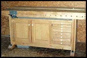
I wanted to use the space underneath the bench for storage, so I built a simple cabinet to fit between the trestles and rest on top of the stretchers. This is a completely separate piece that is held in place only by friction and gravity, but adds considerable mass and stability to the bench, especially when full of tools. The carcass of the cabinet is made of 3/4" plywood, rabbeted, glued and nailed at the corners. The back of the cabinet is 1/4" tempered hardboard set into a rabbet and glued and nailed. There is a single vertical divider set into dados in the top and bottom separating the drawer section from the cupboard section, and a shelf in the cupboard section supported by dados in the divider and end panel, a horizontal cleat attached to the back panel, and a vertical cleat on the inside face of the face frame. The face frame was made from some of the leftover birch, as were the drawer boxes. I installed the face frame with its inner edge flush with the inside of the case so that its outer edge provides a lip that goes up against the front edge of the trestles. I elected to go with 8 shallow drawers rather than 4 deep ones, because I find that deep drawers tend to get cluttered and things get lost in the bottom. I used some ash that I had around for the drawer fronts and paneled doors.
The drawers are side hung on runners, and I let the drawer sides extend 5" or 6" beyond the drawer back so that they are sort of low tech full extension drawers. The drawer bottoms are 1/4" tempered hardboard in a groove in the sides and front, and nailed to the bottom of the drawer back. The sides and front are connected using half blind dovetails cut with my router and Sears dovetail jig. The drawer fronts are flush with the sides on the top and bottom, but overlap the drawer openings by 3/8" on each side for a semi-lipped effect. The cabinet doors are also lipped 3/8" all the way around. I used Danish Oil as a finish on the cabinet as well.
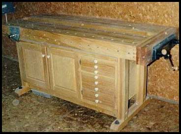
The cabinet was a snug fit between the trestles, so that I had to back off the bolts into the stretchers to slide it into place. Once the bolts were tightened back up, the cabinet was firmly held in position. I installed small porcelain knobs as drawer and door pulls, because they were the cheapest thing I could find, but I very much like the finished look. I have suffered through numerous digs about why my kitchen cabinets don't look this good!
This bench is very heavy and stable. I have placed it in its final position in my shop (unfortunately, up against the wall) and although I have not had enough time to actually use it much yet, I already know that is going to be one of the most valuable additions to my arsenal of tools. It transforms a frustrating operation involving awkward body positions attempting to keep one foot on the base of my Workmate to keep it anchored in place while I push the hand plane into a pleasure. I expect it will also contribute to shop safety, since my most serious injuries to date have all been the result of having a hand chisel slip and hit the hand I was using to hold the workpiece from moving.
I am as proud of this project as I have ever been of anything I have made, and extremely pleased with the way it turned out. I even managed to overcome my tendencies towards procrastination long enough to take pictures and actually get them developed! If nothing else, they prove that I am not much of a photographer.
My costs for this project, in Canadian dollars:
-wood - $131.10 plus a little wood that
I already had on hand.
-Plywood and tempered hardboard for cabinet - ~$50.00
-assorted hardware purchases(hinges, pulls, bolts, etc.) - ~$30.00
-Veritas Twin-screw Vise kit - $155.00 plus taxes
-Veritas Bench Dogs - $42.00 plus taxes for two pairs
-Veritas Bench Pups - $16.95 plus taxes for one pair
-Lee Valley Danish Oil - $40.50 plus taxes for 3 quarts
-assorted shop supplies (screws, nails, biscuits, sandpaper,
etc.) - ~$25.00
Grand total - $490.55 plus the taxes on those items listed above.
I feel that this bench is easily the equivalent of benches or bench kits that sell for $1000.00 plus, and the experience derived from constructing it myself is priceless. The project took me about 2 months to complete, but then I never claimed to be fast.
I would like to take this opportunity to offer my heartfelt thanks to the members of the woodworking listserve at theoak.com who were so generous with their advice and encouragement, and especially to Kip Yeager for providing the forum who made it all possible. Three cheers for Kip!
Bob Hamilton